Search

What Is an Ebike Cable and Which Type Do You Need?

An Ebike Cable may look like a simple wire, yet it carries signals or power through the bicycle. Behind the frame, cables connect the battery, motor, controller, display, brake sensors, and other electrical parts. A loose connector can cause sudden cutouts, error codes, or a display that stays dark. The right replacement depends on the cable’s job, connector shape, pin layout, length, and system voltage. Small differences matter.

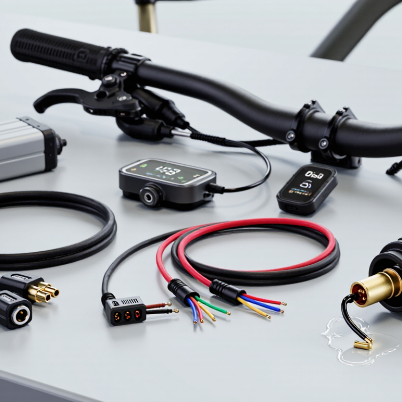
In practical inspections, I look for crushed insulation, bent pins, moisture marks, and strained cables near the handlebar. Motor cables are usually thicker and may include waterproof connectors. Display cables often carry communication signals, while brake-sensor cables can trigger motor cutoff. Battery and power cables require extra care because they handle higher current. Sensor cables may appear similar, but their wiring order can differ between systems. Matching the plug alone is not enough.

Manufacturers may use different names for similar cables. Some labels are unclear. That is where careful checking becomes more reliable than guessing. Record the bicycle’s brand, motor system, connector count, wire colors, and cable length before ordering. A service manual or authorized dealer can confirm compatibility when specifications conflict. I have found that even experienced owners can overlook one small pin. This guide explains the main Ebike Cable types, how they function, and which details deserve attention before installation. It will not replace professional service when wiring is damaged or battery connections are involved, but it can make the decision clearer and safer.

What Is an Ebike Cable and Which Type Do You Need?

What an Ebike Cable Is and How It Connects the System

What Is an Ebike Cable and Which Type Do You Need?

An ebike cable carries power or signals between the battery, controller, motor, display, and sensors. It is more than a simple wire. Each cable uses specific conductors, connectors, and insulation for its job. Thick power cables handle battery current, while thinner signal cables carry speed or control data. Motor phase cables often contain three heavy wires. Smaller sensor cables may include five or six pins.

Cable selection depends on voltage, current, connector shape, pin layout, and cable length. A connector can fit physically but still use a different pin arrangement. That mistake may damage a controller or sensor. Check the wiring diagram before connecting anything. Inspect the plug for bent pins, loose seals, or moisture near the contacts. Outdoor riding exposes cables to rain, grit, and repeated movement.

Routing also affects reliability. Keep cables away from sharp frame edges and hot surfaces. Leave enough slack near the handlebar for full steering movement. I once saw a cable fail because it was pulled tight during a turn. The fault looked like a battery problem at first. Cable labels are useful, but they are not always accurate. Confirm each connection with a meter and the system’s technical documentation.

Disconnect the battery before checking or replacing wiring.

The Main Types of Ebike Cables and Their Functions

What Is an Ebike Cable and Which Type Do You Need?

An ebike cable is more than a simple wire. It carries power, sensor signals, or control commands between major electrical components. The correct type depends on its function, connector, voltage, and current capacity.

Motor phase cables are usually three thick wires. They deliver high current from the controller to the motor. Hall sensor cables are thinner and transmit rotor-position signals. Battery cables carry significant power, so damaged insulation deserves immediate attention. Display and communication cables connect the control panel with the controller. Brake cutoff cables are smaller, but they can interrupt motor assistance when a lever is pressed. Charger cables must match the battery’s voltage and charging system exactly.

The International Energy Agency reported over 50 million electric two- and three-wheelers on the world’s roads in 2023. That growth increases the need for dependable wiring inspections. The U.S. Consumer Product Safety Commission recorded 233 deaths involving micromobility products from 2017 to 2022, showing why electrical maintenance should not be casual.

Check the pin count first. Then check polarity, wire thickness, connector sealing, and routing near moving parts. A cable may look compatible and still carry the wrong signal. Cable charts help, but they are not infallible. I would avoid forcing any connector. One bent pin can create an intermittent fault that appears only during riding. The safest replacement matches the original specification, not merely its shape.

How to Match a Cable with Your Ebike Components

An ebike cable is more than a wire with a matching plug. It connects important components, such as the battery, controller, display, motor, brake sensor, or throttle. Each connection may require different voltage, current capacity, pin arrangement, and communication signals. A connector can fit physically and still be electrically wrong. Never rely on appearance alone.

Start by identifying the component at both ends of the cable. Check the voltage rating, connector shape, pin count, wire thickness, and cable length. The battery-to-controller cable usually needs thicker conductors than a display cable. Motor cables may include several power wires and smaller sensor wires. Brake and shift cables are mechanical, not electrical, so they need correct housing length, inner-wire size, and smooth routing. Measure twice.

Cable routing also matters. A cable stretched around the handlebar can pull during steering. A loose cable may touch the tire, chain, or a hot surface. Look for sealed connectors when riding in wet conditions, but do not assume every sealed plug is waterproof. A small gap can admit moisture. One common workshop error is choosing a cable because its connector fits. I have seen this assumption cause confusing faults, and careful pinout checking would have prevented them. Even accurate measurements can be imperfect, so leave modest routing slack and inspect the connection after installation.

Signs of Cable Damage, Wear, or Compatibility Problems

An ebike cable carries power or signals between key electrical and control components. Common examples include battery, motor, display, brake-sensor, and charging cables. Their connectors may look similar, but their functions can differ greatly.

During workshop inspections, I look for damage before checking performance.

Safety comes first.

Watch for cracked insulation, flattened sections, exposed copper, loose connectors, or green residue near terminals. These signs often indicate moisture, corrosion, or repeated bending.

Flickering displays, sudden motor cutouts, weak braking signals, and charging interruptions can also suggest cable trouble. Heat around a connector deserves immediate attention. Do not ignore it.

Compatibility problems are less obvious. Check the connector shape, pin count, cable length, voltage rating, and communication type.

A cable that fits physically may still send the wrong signals. I once assumed a matching plug guaranteed compatibility. That shortcut was wrong.

It caused intermittent faults that appeared only during riding. Power off the ebike and remove the battery before inspection.

Replace damaged wiring with the correct specification, not merely a similar-looking cable. For uncertain wiring, ask a qualified technician to test continuity and connector condition.

A small mismatch can become an expensive repair.

How to Choose and Replace the Right Ebike Cable

An ebike cable is not always a simple wire. It may control braking, shifting, motor signals, display data, or battery power. Each cable has a different purpose and connector. Using the wrong type can cause weak braking, error codes, or electrical damage.

Choose a replacement by matching its function, length, connector shape, wire count, and weather protection. For a mechanical brake, measure the inner cable and outer housing separately. The cable should move smoothly without sharp bends. For electrical wiring, match the connector and wire rating exactly. Never force a plug into place. I once found that a similar-looking connector fitted loosely, but vibration caused intermittent motor cuts. That mistake was avoidable.

Tips: Turn off the system and remove the battery before handling electrical cables. Photograph the original routing. Keep wires away from the chain, tire, and hot surfaces. After replacement, test the brakes while standing still, then ride slowly in a safe area. Check every connector again after the first short ride. A cable may look correct yet fail under movement. If the wiring is damaged near the battery or motor, professional inspection is the safer choice.

What Is an Ebike Cable and Which Type Do You Need? — How to Choose and Replace the Right Ebike Cable

Cable Type Main Function Typical Construction Common Identification Features Important Sizing or Compatibility Checks Common Replacement Signs Replacement Guidance
Mechanical Brake Cable Transfers force from a brake lever to a mechanical disc or rim brake. Inner wire: Usually stainless steel or galvanized steel.
Housing: Compression-resistant brake housing.
Usually has a brake-lever end fitting. The fitting shape can differ between flat-bar and drop-bar levers. Match the lever-end fitting, housing diameter, total length, and brake type. Brake housing should not be replaced with ordinary shift housing. Frayed strands, rust, sticky lever movement, delayed braking, cracked housing, or excessive lever travel. Replace the inner wire and inspect the housing at the same time. Cut housing cleanly and install ferrules where required.
Mechanical Shift Cable Moves a derailleur or internal-gear mechanism when the rider changes gears. Inner wire: Thin stainless steel or galvanized steel wire.
Housing: Low-compression shift housing.
Commonly uses a small barrel-shaped shifter-end fitting. The rear derailleur end is normally plain and is cut after installation. Confirm shifter-end fitting, cable length, housing routing, and compatibility with the gear-control system. Do not use brake housing for precise shifting. Slow shifting, missed gears, noisy drivetrain, corrosion, fraying, or a cable that no longer returns smoothly. Replace the cable if strands are damaged. Set the barrel adjuster near the middle of its range before indexing the gears.
Motor Phase Cable Carries high-current power from a brushless motor controller to the motor windings. Conductors: Typically three heavy-gauge phase wires.
Protection: Insulation, sleeving, and often a sealed connector.
Usually thicker than sensor wires and often routed toward the motor axle. It may have three separate high-current terminals or a combined connector. Match conductor count, wire gauge, connector shape, keying, pin arrangement, voltage and current rating, and waterproofing. Disconnect the battery before inspection. Motor cut-outs under load, overheating, melted insulation, discoloration, intermittent power, or error codes after cable movement. Use a cable rated for the system’s current. Never rely only on wire color; confirm the pinout with the system documentation or a qualified technician.
Motor Hall Sensor Cable Sends rotor-position signals from the motor to the controller for motor commutation. Conductors: Commonly five or six low-voltage signal wires.
Protection: Small insulated conductors inside a multi-core cable.
Much thinner than phase wiring and commonly paired with a small multi-pin connector near the motor or controller. Check the number of conductors, connector keying, pinout, voltage level, cable length, and whether the motor uses Hall sensors or a sensorless control system. Jerky starting, motor vibration, failure to start, intermittent operation, or controller faults related to motor position sensing. Do not substitute a phase cable for a Hall cable. Inspect for damage near the axle, where repeated flexing can break internal conductors.
Display or Handlebar Control Cable Connects the display, power button, mode controls, or remote buttons to the controller. Conductors: Low-voltage multi-core signal wires.
Jacket: Flexible outer insulation for handlebar movement.
Often uses a small keyed waterproof connector. Cable assemblies may include a display plug, button remote, or combined control lead. Match connector type, number of pins, pin arrangement, communication protocol, cable length, and operating voltage. Similar-looking plugs may not be electrically compatible. Blank display, buttons that work intermittently, power loss when the handlebar turns, or visible connector corrosion. Route with enough slack for full steering movement. Avoid tight bends, sharp edges, and clamping the cable under the stem or handlebar.
Brake-Cutoff Sensor Cable Signals the controller to stop motor assistance when a brake lever is pulled. Conductors: Usually a low-voltage two- or three-wire sensor lead.
Sensor: Mechanical switch or magnetic sensor.
May be integrated into the brake lever or attached externally with a magnet and sensor body. Confirm sensor style, connector, normally-open or normally-closed operation, pinout, and compatibility with the controller’s brake-input circuit. Motor assistance does not stop, assistance cuts out unexpectedly, or the controller displays a brake-sensor fault. Test the brake cutoff before riding. A damaged sensor should not be bypassed unless the system is designed and approved for operation without it.
Pedal-Assist Sensor Cable Connects the pedal-assist sensor to the controller and carries cadence or position signals. Conductors: Commonly three low-voltage wires for power, ground, and signal.
Sensor: Magnetic cadence or torque-sensing assembly.
Usually routed around the bottom bracket and connected to a small sensor plug near the controller. Check sensor type, connector, pinout, mounting orientation, cable length, and controller compatibility. Cadence and torque sensors are not interchangeable. Assistance starts late, cuts in and out, remains active after pedaling stops, or fails to activate. Keep the cable away from the chain, crank, and bottom-bracket movement. Replace damaged connectors rather than forcing mismatched plugs together.
Battery Power Cable Transfers electrical power between the battery, controller, charging interface, or protected distribution point. Conductors: Usually two heavy power conductors, with separate low-voltage communication leads on some systems.
Protection: High-current insulation and an appropriately rated connector.
Thicker conductors, polarized connectors, locking plugs, and sometimes an inline fuse or battery-management connection. Match nominal voltage, continuous and peak current rating, connector polarity, terminal size, locking method, cable gauge, and battery-management-system requirements. Power interruptions, hot connectors, arcing, melted plastic, burnt odor, exposed copper, or battery shutdown under load. Remove the battery before servicing. Never reverse polarity or connect a cable with an unknown voltage rating.
Charging Cable or Charging-Port Lead Connects the charger to the ebike battery or charging port. Conductors: Two power conductors are common, although some systems use additional contacts.
Protection: Insulated cable and a keyed or threaded charging connector.
Smaller than the main battery cable and located near the charging socket or battery enclosure. Match charger output voltage, charging-current rating, connector polarity, plug dimensions, locking style, and battery-management requirements. Charging stops intermittently, the plug becomes hot, the port is loose, pins are bent, or the charger reports a connection fault. Use only a charger and cable designed for the battery system. Keep the port dry and do not charge through a damaged or contaminated connector.
Lighting or Accessory Cable Supplies power or control signals to lights, a horn, a USB outlet, or another low-power accessory. Conductors: Commonly two wires for power, with additional signal wires in some accessories.
Protection: Flexible insulated cable, sometimes with a sealed connector.
Usually thinner than motor and battery wiring and routed toward the front or rear accessory. Check output voltage, maximum current, polarity, connector, cable length, and whether the controller provides a switched or always-on supply. Flickering lights, accessory failure, intermittent operation while steering, damaged insulation, or a blown fuse. Do not connect a low-voltage accessory directly to a high-voltage battery unless a suitable converter and protection are specified.

Selection rule: Before ordering a replacement, compare the original cable’s function, connector, pin arrangement, electrical rating, cable length, routing, and sealing level. Similar connector shapes do not guarantee electrical compatibility.